


Introduction
Three-dimensional (3D) printing has made great strides in recent years. Although the models cannot yet replace organs, they are very useful in modelling osseous structures. The affordability and accessibility of 3D printing have increased [1], but it has not yet achieved everyday usage.
The process of 3D printing involves two steps. First, stacked computed tomography (CT) or magnetic resonance images in Digital Imaging and Communications in Medicine (DICOM) format are converted to stereolithography (STL) that describes the 3D surface geometry. Then, a 3D model is printed. Some printers now cost less than $1,000. However, most surgeons are not familiar with the software required for the first step of 3D printing. Most medical researchers use Mimics (Materialise, Leuven, Belgium) [2-6], which shows excellent performance. However, a license costs $10,000 to $20,000 depending on the modules included.
Therefore, we developed a 3D printing workflow using open-source software and an affordable desktop printer. This can be achieved in a typical office setting. As George et al. [7] proposed, we need to establish the accuracy and reproducibility of our workflow. We performed a prospective study on patients with distal radius fractures to investigate whether the printed models resembled actual bones.
Methods
Ethics statement: This retrospective study was approved by the Institutional Review Board of Seoul National University College of Medicine and Seoul National University Hospital (No. H-2105-093-1219). Informed consent was written by all enrolled patients.
1. Sample size estimation
A distal radius fracture displacement of >2 mm is considered significant [8]. Screw sizes vary in steps of 1 or 2 mm. We thus determined the non-inferiority margin (δ), which was 1. The standard deviation of the anterior-to-posterior (AP) size was the same as in a previous cadaver study [9]. Our hypotheses were as follows:
H0 size at fracture site (3D simulation) minus size at fracture site (real surgery) ≤−|δ|
H1 size at fracture site (3D simulation) minus size at fracture site (real surgery) >−|δ|.
2. Patient enrolment
Patients were consecutively enrolled beginning in October 2021. We invited adult patients with distal radius fractures admitted for surgery to participate. Fractures with severe comminutions (AO/OTA classes 23-C2 and C3) were excluded [12]. Seven patients gave written informed consent by February 2022.
3. Three-dimensional printing
An IQon Spectral CT scanner (Philips, Amsterdam, Netherlands) was used. Preoperative wrist CT yields images in DICOM format that can be converted into STL images using 3D Slicer (ver. 4.11; Surgical Planning Laboratory, Harvard Medical School, Boston, MA, USA) [13]. Segmentation converts stacked two-dimensional images (in DICOM format) into 3D surface models (STL format) [14]. The process is as follows: the DICOM files to be converted are selected. Usually, the thinnest axial images are ideal. We obtained 299 images per patient, each with a thickness of 0.8 mm. Then, a segmentation editor is used to select an appropriate threshold for the region of interest; only the osseous portion should undergo volumetric reconstruction. After clicking on the 3D icon, the model appears. If only the distal radius is of interest, the “scissors” and “island” functions can be used to crop away other carpal bones and/or the ulna. Finally, the final 3D model is exported as an STL file (Fig. 1). The file must then be converted into geometric (G)-code to command the printer. We used Cura (ver. 4.11.0; Ultimaker, Utrecht, the Netherlands) to this end. This open-source slicing application converts STL to G-code that instructs the 3D printer. The default settings should be used, i.e. 0.2-mm thickness and 10% occupied volume. Clicking the slice icon yields G-code that is then sent to an Ender-5-Plus 3D printer (Shenzhen Creality 3D Technology, Shenzhen, China) using polylactic acid filament as ink. The product is a printed 3D model of the fractured distal radius. Fig. 2 summarizes these steps.
4. Measurement of parameters
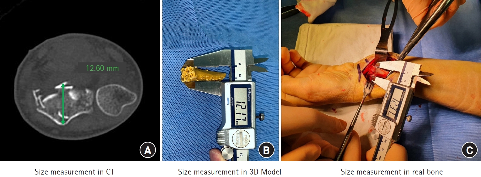
The AP and radial-to-ulnar (RU) widths (in mm) of the fracture sites were measured on CT images, printed models, and real bones (during surgery) (Fig. 3).
(1) To obtain measurements on CT images, the “ruler” of the picture archiving and communication system was used. The fracture site was selected in an axial cut by browsing the coronal and sagittal sequences. At the appropriate axial image, AP and RU widths between the farthest cortices were measured (Fig. 3A).
(2) After 3D models were produced, the models were separated at the fracture sites. We used a digital caliper to measure the AP and RU widths at the distal end of proximal fragments (fracture site) in the printed models (Fig. 3B).
(3) We used the same caliper (now sterilized) to measure real bones during surgery. Similarly, these measurements were also made by holding the distal end of proximal fragments with the caliper before the reduction (Fig. 3C). A gentle periosteal dissection at the fracture site facilitated the measurement using a caliper, which in turn made the reduction also simple.
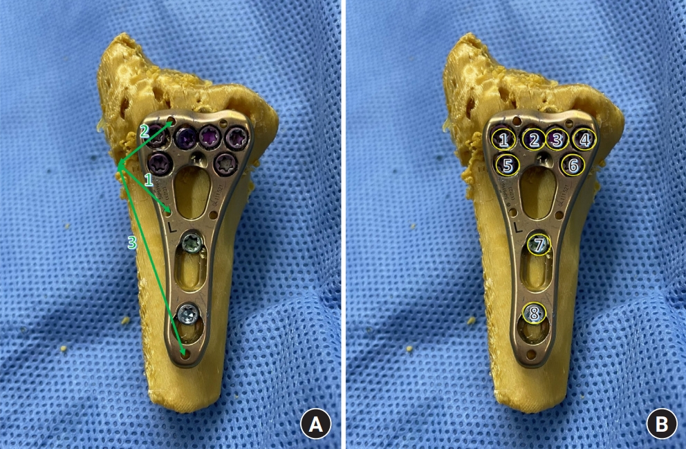
We recorded the times required for modeling, printing, and simulation. Modeling refers to the conversion of the DICOM file to G-code. Reduction and fixation of printed distal radii (using plates and screws) were simulated by the junior orthopedic surgeon (author 1). During simulation and surgery, narrow or standard 2.4-mm variable angle locking compression plates and volar distal radius plates (DePuy Synthes, Warsaw, IN, USA) with two shaft holes were used. Each plate was secured with 2.4-mm variable angle locking screws. Plate locations were recorded by measuring three distances (location, sLOC [and rLOC] 1, 2, and 3) (Table 1, Fig. 4A) from the radial margins of the fracture site to the wire holes. If all three distances were similar during simulation and real surgery, we assumed that the plate locations would be similar. The screw lengths (ssc [and rsc] 1 to ssc [and rsc] 8) (Table 2, Fig. 4B) were recorded. The senior orthopedic surgeon (author 2), who was blinded to the simulation data, performed all surgeries. The corresponding plate profiles and screw sizes during the surgery were recorded.
5. Statistical analysis
Measurements were compared using the signed-rank test. When no significant difference was apparent, measurement consistency was further evaluated by calculating interclass correlation coefficients (ICCs). All statistical tests were two-tailed and p-values of <0.05 were considered significant.
Results
Modeling required an average of 8 minutes (range, 6-9 minutes). Printing required an average of 149 minutes (range, 99–225 minutes) but was not supervised. The simulation required an average of 19 minutes (range, 12–26 minutes).
1. Fracture site sizes
The CT, 3D model, and real bone AP and RU widths did not differ significantly (Table 3). The ICC revealed excellent consistency among the measurements.
2. Implant profiles
For cases 1 to 5, narrow plates were used for both simulation and real surgery; while standard plates were employed for cases 6 and 7. Distance 2 was significantly shorter during real surgery than simulation (mean sLOC2, 16.04 mm vs. mean rLOC2, 14.69 mm; p=0.043) (Table 1). In terms of screw sizes, the most distal and radial screw, i.e. screw 1, was significantly longer in the simulation compared with real surgery (mean ssc1, 17.42 mm vs. mean rsc1, 14.29 mm; p=0.016) (Table 2). The sizes of other screws did not differ significantly, but only the two screws for the shaft holes had ICCs indicating excellent consistency (0.927 and 0.842, respectively).
Discussion
In this study, we introduced an efficient and affordable 3D printing workflow. The only cost is associated with the hardware (about $600). In our prospective study of seven distal radius fractures, the models matched the real bones excellently. CT is generally used to measure bone size [15]. The integrity of CT DICOM files is extremely high. However, a divergence in a given DICOM file may be seen among institutes due to the STL file conversion process [16]. In another study, a single institute using nine different software packages noted no significant divergence [14]. This supports the necessity of establishing the accuracy and reproducibility for each 3D printing workflow [7]. The 3D Slicer free open-source software is supported by international developers [13]. The pioneering Quantitative Imaging Network (QIN) uses 3D Slicer for personalized cancer therapy. The QIN group includes the Brigham and Women’s Hospital, the University of Iowa, and Massachusetts General Hospital. Bagaria and Chaudhary [17] reported their experience with 3D Slicer; subjective feedback from five surgeons indicated that the models accurately reflected the actual anatomies. Our study is the first to show that fractured bone geometry is preserved by a workflow using a 3D Slicer.
3D printing technology is evolving rapidly but is currently used by only a few large centers [18]. Perceived barriers to widespread use include high monetary and time costs. Printers range in price from $100–$10,000. Most devices that cost less than $1,000 can produce bone models. Open-source software, such as 3D Slicer and Cura, show excellent modeling performance, and there are no additional labor costs because clinicians perform all functions. In this study, the average modeling time was 8 minutes. Printing took over 2 hours but was not supervised. One kilogram of ink costs $10, and there are no maintenance costs. Also, the printer is small and we use it to create one or two 3D models daily in our office; even small private practices can use our workflow.
In this study, we focused on introducing and validating our 3D printing workflow rather than an emphasis on preoperative planning. The senior surgeon lacked knowledge of the simulation performed by the junior surgeon. The plate location differed significantly between the simulation and real surgery, but the length of only one screw differed significantly. Preoperative planning is essential; previous studies on die-punch, intercondylar distal humeral, and complex proximal humeral fractures found that preoperative planning (via 3D printing) significantly reduced blood loss, operative time, and the number of intraoperative fluoroscopies [4-6]. Yoshii et al. [19] reported that the 3D preoperative plans (without printing) for the treatment of distal radius fractures exhibited errors of about 2 mm. A recent systematic review on preoperative planning prior to reverse total shoulder arthroplasty also revealed minimal real-world deviations from such plans [20]. The utility of 3D printing when performing bone surgery is thus well-recognized, but accessibility must be improved.
There are limitations to our study. This is a prospective study, but the minimum number of patients according to the power analysis were enrolled. Second, the clinical evidence of simulation using this workflow has not been properly investigated in this study. In the absence of soft tissue, the simulation using the model inherently differs from the actual surgery. The simulation cannot reflect the surgical approach, dissection, and reduction of fracture when there are ligaments and tendons surrounding the target. A more elaborate model reflecting these obstacles should be investigated further. Also, the simulator and the surgeon who operated the actual cases were different. Ideally, the simulator and the surgeon should be the same person, and parameters like operation time, bleeding amount, and radiographic measurement should be compared. However, this kind of investigation belongs to clinical investigation of medical devices. This research will provide the background for our next research which will be the clinical investigation of medical devices for the treatment effect of our 3D printing workflow.